
Main menu

  • HOME
  • CONTENT
    • Early Release
    • Featured
    • Current Issue
    • Issue Archive
    • Blog
    • Collections
    • Podcast
  • TOPICS
    • Cognition and Behavior
    • Development
    • Disorders of the Nervous System
    • History, Teaching and Public Awareness
    • Integrative Systems
    • Neuronal Excitability
    • Novel Tools and Methods
    • Sensory and Motor Systems
  • ALERTS
  • FOR AUTHORS
  • ABOUT
    • Overview
    • Editorial Board
    • For the Media
    • Privacy Policy
    • Contact Us
    • Feedback
  • SUBMIT

User menu

Search

  • Advanced search
eNeuro

eNeuro

Advanced Search


  • HOME
  • CONTENT
    • Early Release
    • Featured
    • Current Issue
    • Issue Archive
    • Blog
    • Collections
    • Podcast
  • TOPICS
    • Cognition and Behavior
    • Development
    • Disorders of the Nervous System
    • History, Teaching and Public Awareness
    • Integrative Systems
    • Neuronal Excitability
    • Novel Tools and Methods
    • Sensory and Motor Systems
  • ALERTS
  • FOR AUTHORS
  • ABOUT
    • Overview
    • Editorial Board
    • For the Media
    • Privacy Policy
    • Contact Us
    • Feedback
  • SUBMIT
PreviousNext
Research ArticleResearch Article: Methods/New Tools, Novel Tools and Methods

Application of 3D Printing Technology to Produce Hippocampal Customized Guide Cannulas

Maria Rosaria Tropea, Alberto Torrisi, Valeria Vacanti, Danilo Pizzone, Daniela Puzzo and Walter Gulisano
eNeuro 14 September 2022, 9 (5) ENEURO.0099-22.2022; DOI: https://doi.org/10.1523/ENEURO.0099-22.2022
Maria Rosaria Tropea
1Department of Biomedical and Biotechnological Sciences, University of Catania, 95123 Catania, Italy
  • Find this author on Google Scholar
  • Find this author on PubMed
  • Search for this author on this site
  • ORCID record for Maria Rosaria Tropea
Alberto Torrisi
1Department of Biomedical and Biotechnological Sciences, University of Catania, 95123 Catania, Italy
  • Find this author on Google Scholar
  • Find this author on PubMed
  • Search for this author on this site
Valeria Vacanti
1Department of Biomedical and Biotechnological Sciences, University of Catania, 95123 Catania, Italy
  • Find this author on Google Scholar
  • Find this author on PubMed
  • Search for this author on this site
Danilo Pizzone
1Department of Biomedical and Biotechnological Sciences, University of Catania, 95123 Catania, Italy
  • Find this author on Google Scholar
  • Find this author on PubMed
  • Search for this author on this site
Daniela Puzzo
1Department of Biomedical and Biotechnological Sciences, University of Catania, 95123 Catania, Italy
2Oasi Research Institute-Istituto di Ricovero e Cura a Carattere Scientifico (IRCCS), 94018 Troina, Italy
  • Find this author on Google Scholar
  • Find this author on PubMed
  • Search for this author on this site
Walter Gulisano
1Department of Biomedical and Biotechnological Sciences, University of Catania, 95123 Catania, Italy
  • Find this author on Google Scholar
  • Find this author on PubMed
  • Search for this author on this site
  • Article
  • Figures & Data
  • Info & Metrics
  • eLetters
  • PDF
Loading

Article Figures & Data

Figures

  • Tables
  • Extended Data
  • Figure 1.
    • Download figure
    • Open in new tab
    • Download powerpoint
    Figure 1.

    Representation of head mount and guides. a, Photograph of a cannula of our production. b, Rendered image of an assembled cannula. c, Exploded isometric view of the components and key parameters of a guide cannula. d, Technical drawing of the head mount, including all of the relevant dimensions. All measures are expressed in millimeters. e, Left and right guides measured in 26 cannulas have the correct expected length of 1330 μm. Data are expressed as mean ± SEM.

  • Figure 2.
    • Download figure
    • Open in new tab
    • Download powerpoint
    Figure 2.

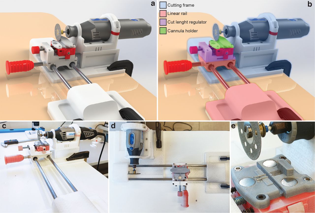
    Linear motion-cutting system. a, Rendered representation of the cutting system. b, Colored highlight of the single components, as follows: (1) light blue, the cutting frame, formed by a base to host the final part of the linear rail and a support for the handheld rotary tool (Dremel); (2) pink, the linear rail, consisting of two 8 mm steel bars held by 3D-printed components to form a sliding carriage; (3) violet, the cut length regulator allowing determination of the length of the guides; and (4) green, the cannula holder placed on top of the carriage to host and hold the head mount in place during the cutting process. c–e, Photographs with front, top, and closeup views of the actual apparatus built in our laboratory.

  • Figure 3.
    • Download figure
    • Open in new tab
    • Download powerpoint
    Figure 3.

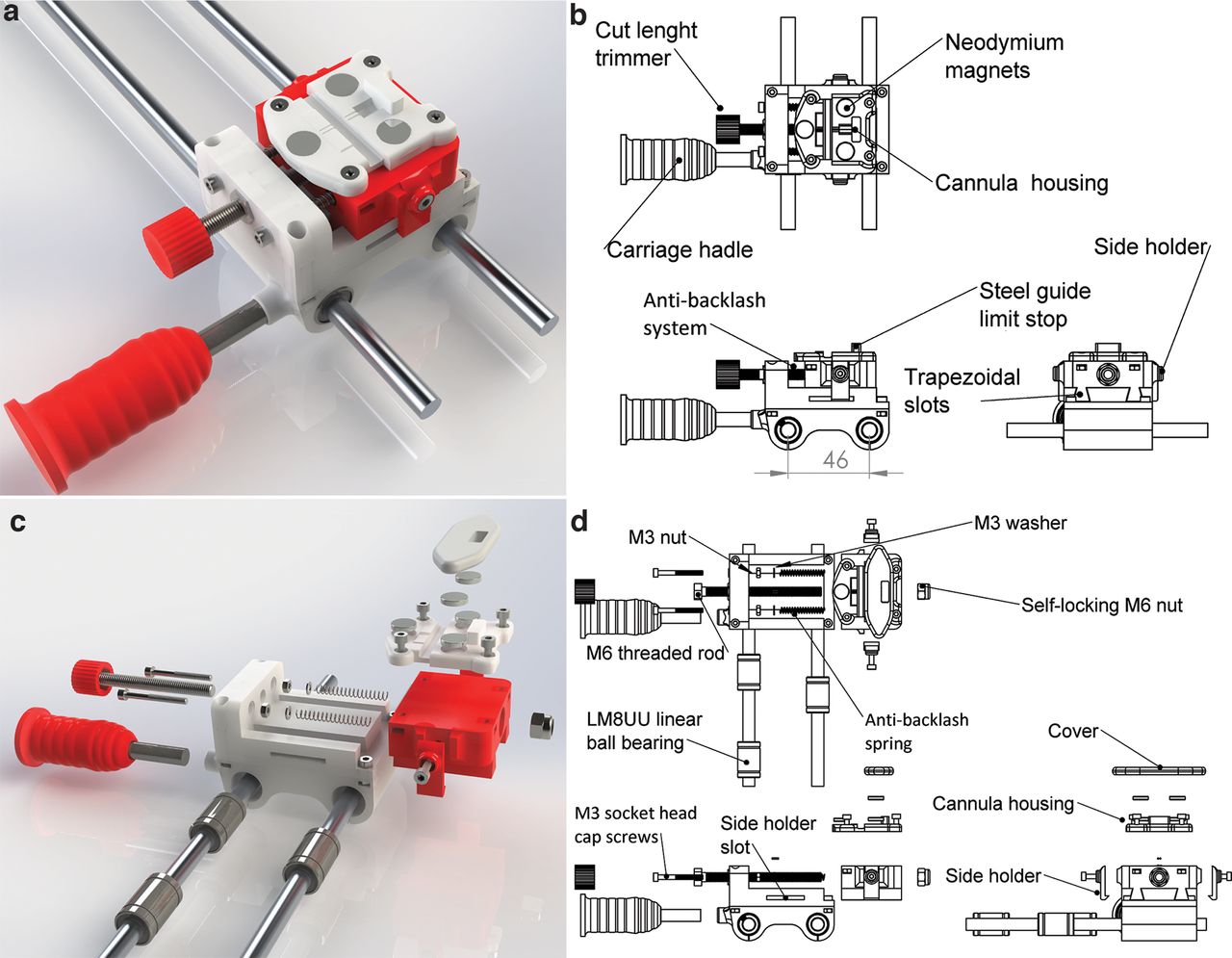
    Descriptive images of the cutting frame and the linear rail. a, Rendered image of the isolated cutting frame clamped to the table. b, Schematic drawing of the cutting frame. The rotary tool support is mounted on the base and fixed to a structure that can be moved to modify the position of the cutting blade and host air vents to avoid overheating. The rotary tool is equipped with a 38 mm circular diamond-coated blade. c, Rendered image of the linear rail and the base of the cutting frame, both clamped to the table. d, Schematic drawing of the linear rail that is composed of two parallel 8 × 270 mm bars with a 46 mm interaxial distance. The carriage consists of a base with two blind holes hosting three LM8UU linear ball bearings, two on one side and one on the other side to ensure a straight alignment of the 8 mm bars. The base is equipped with a 3D-printed handle to move the carriage back and forth along the linear rail. Another carriage is mounted on the top of the base by four socket head cap M3 screws.

  • Figure 4.
    • Download figure
    • Open in new tab
    • Download powerpoint
    Figure 4.

    Cutting length regulator. a, Rendered image of the cutting length regulator, consisting of two main parts, both 3D printed. b, Schematic drawing of the cutting length regulator. The moving part is inserted into its base by two trapezoidal slots. c, Rendered exploded view of the cutting length regulator. d, Schematic drawing of the exploded view in c. The displacement of the carriage is granted by the following two components: an M6 threaded rod, passing through the base and the carriage, with a self-locking M6 nut; an antibacklash system composed of two M3 socket head cap screws supporting two springs pushing from the surface of the base to the inside of the carriage. The carriage can be moved by turning the screw and is held in place by the tension of the springs. Two holders are placed on the side of the carriage fixing it to the base.

  • Figure 5.
    • Download figure
    • Open in new tab
    • Download powerpoint
    Figure 5.

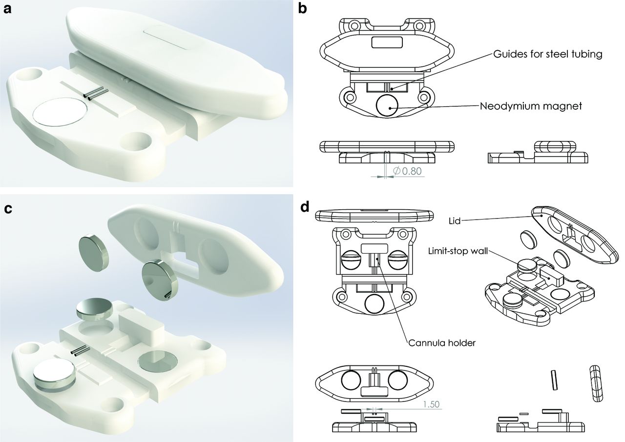
    Cannula holder. a, Rendered image of the cannula holder. b, Schematic drawing of the cannula holder formed by a base and a lid. The base, designed to host the cannula head mount, shapes its octagonal form and presents with grooves for the guide cannulas to stay in place. c, Rendered exploded view of the cannula holder. d, Schematic drawing of the exploded view in c. The cannula holder hosts 10.2 × 2.2 mm cylindrical neodymium magnets. Two magnets are inserted on the base of the cannula holder, two on the lid, and one in front of the guides.

  • Figure 6.
    • Download figure
    • Open in new tab
    • Download powerpoint
    Figure 6.

    Illustrated step-by-step process of the cutting procedure. a, Positioning of cannula body in its holder with the open side facing the end limit wall. The head mount body should be placed into its housing shaped in the cannula holder oriented as shown in the insert. b, Regulation of the cutting length. Carriage is pushed underneath the blade (multitool turned off), and its relative position is adjusted to the blade. For optimal positioning, the blade is as close as possible to the cannula without touching it. c, Positioning of the steel guides and the head mount shell. The carriage is placed back into a safe position. Steel tubes (spinal needles) are inserted into the head mount through the appropriate guides until they reached the limit stop represented by the wall behind the cannula. A drop of superglue is placed on the cannula body and is covered by the shell part of the cannula to let the head mount be assembled. d, Positioning of the magnetic lid to ensure a tight compression on the head mount ensured by the magnets. e, Cutting of the steel guides at the appropriate length. The rotary tool (Dremel) is turned on at ∼5000 rpm. The main carriage is pushed to the rotating blade cutting the guides. After cutting, the carriage is moved back to the starting position, the rotary tool is stopped, and the lid is removed to extract the cannula.

  • Figure 7.
    • Download figure
    • Open in new tab
    • Download powerpoint
    Figure 7.

    Intrahippocampal cannula validation. a, Mouse brain after cannula removal. Guide holes are equidistant from the interhemispheric fissure. b, Injections of methylene blue in the right hemisphere reaching the CA1 area. c, Nissl staining of the coronal section of a mouse left hemisphere. The cannula lesion is visible above the hippocampus. d, In mice implanted with commercial cannulas, intrahippocampal injections of 200 pm Aβ increased the discrimination index, whereas injection of 200 nm Aβ impaired it. e, The same results are obtained in mice infused through our homemade cannulas. f, g, Total exploration time is not modified by treatment in mice injected by commercial (f) or homemade (g) cannulas. *p < 0.05; **p < 0.01. Data are expressed as the mean ± SEM.

Tables

  • Figures
  • Extended Data
    • View popup
    Table 1

    Bill of materials for the cutting apparatus

    ItemDescriptionQuantityCost (€)
    3D printerAny FDM with sufficient build volume1400–1500
    Stainless steel rod200–300 mm, Ø, 8 mm210
    Linear ball bearingLM8UU Ø, 8 mm35–10
    Neodymium magnetsCylindrical 10 × 2 mm52
    C- ClampsSize depends on the mounting surface420
    Screws, nuts, washers and springsSupplementary informationSupplementary information30
    MultitoolDremel rotary tool or equivalent150–100
    Blade and blade supportDiamond coated130
    Total550–1700
    • The required hardware for building the cutting apparatus and start the cannula production. All costs are expressed in euros.

    • View popup
    Table 2

    List of the required 3D-printed parts for building the cutting apparatus

    ItemQuantityProductionCost (€)
    Bottom rail support14 h 30 min2.30
    Top rail support17 h4.20
    Multitool positioner13 h 30 min1.20
    Multitool support15 h1.70
    Multitool tightener150 min0.30
    Multitool spacer210 min (20 min total)0.05 (0.10 total)
    Base carriage12 h 15 min0.70
    Length regulator base11 h 50 min0.65
    Length regulator11 h 45 min0.50
    Centering support210 min (20 min total)0.025 (0.05 total)
    Cannula support: hippocampus140 min0.20
    Cannula support: cover115 min0.10
    Cutting length: regulator handle120 min0.05
    Carriage handle11 h 20 min0.30
    Total30 h12.35
    • All production times are derived from the following printing parameters: speed = 60 mm/s; layer height = 200 μm; infill = 20%; nozzle diameter = 400 μm. Different parameters will influence printing times. Reported costs are an estimate, based on that of generic PLA. All costs are expressed in euros.

    • View popup
    Table 3

    Production costs and times for differently sized cannula batches

    Cannulas (n)Estimated print timePrint costEstimated time for assembly, cut and validationTotal cost (€)
    111 min40.3
    550 min0.02201.52
    101 h 40 min0.0440 min3.04
    203 h 15 min0.081 h 20 min6.08
    406 h 30 min0.172 h 40 min12.17
    508 h0.213 h 20 min15.21
    10016 h0.46 h 40 min30.4
    • Total cost includes the price of the steel guides. All costs are expressed in euros.

Extended Data

  • Figures
  • Tables
  • Figure 1-1

    Detailed step-by-step building guide for the linear motion-cutting system. Download Figure 1-1, DOCX file.

  • Figure 2-1

    *.Stl files, *.STEP files, and technical drawings. Download Figure 2-1, ZIP file.

Back to top

In this issue

eneuro: 9 (5)
eNeuro
Vol. 9, Issue 5
September/October 2022
  • Table of Contents
  • Index by author
  • Ed Board (PDF)
Email

Thank you for sharing this eNeuro article.

NOTE: We request your email address only to inform the recipient that it was you who recommended this article, and that it is not junk mail. We do not retain these email addresses.

Enter multiple addresses on separate lines or separate them with commas.
Application of 3D Printing Technology to Produce Hippocampal Customized Guide Cannulas
(Your Name) has forwarded a page to you from eNeuro
(Your Name) thought you would be interested in this article in eNeuro.
CAPTCHA
This question is for testing whether or not you are a human visitor and to prevent automated spam submissions.
Print
View Full Page PDF
Citation Tools
Application of 3D Printing Technology to Produce Hippocampal Customized Guide Cannulas
Maria Rosaria Tropea, Alberto Torrisi, Valeria Vacanti, Danilo Pizzone, Daniela Puzzo, Walter Gulisano
eNeuro 14 September 2022, 9 (5) ENEURO.0099-22.2022; DOI: 10.1523/ENEURO.0099-22.2022

Citation Manager Formats

  • BibTeX
  • Bookends
  • EasyBib
  • EndNote (tagged)
  • EndNote 8 (xml)
  • Medlars
  • Mendeley
  • Papers
  • RefWorks Tagged
  • Ref Manager
  • RIS
  • Zotero
Respond to this article
Share
Application of 3D Printing Technology to Produce Hippocampal Customized Guide Cannulas
Maria Rosaria Tropea, Alberto Torrisi, Valeria Vacanti, Danilo Pizzone, Daniela Puzzo, Walter Gulisano
eNeuro 14 September 2022, 9 (5) ENEURO.0099-22.2022; DOI: 10.1523/ENEURO.0099-22.2022
del.icio.us logo Digg logo Reddit logo Twitter logo Facebook logo Google logo Mendeley logo
  • Tweet Widget
  • Facebook Like
  • Google Plus One

Jump to section

  • Article
    • Abstract
    • Significance Statement
    • Introduction
    • Materials and Methods
    • Results
    • Discussion
    • Acknowledgments
    • Footnotes
    • References
    • Synthesis
  • Figures & Data
  • Info & Metrics
  • eLetters
  • PDF

Keywords

  • 3D printing
  • behavioral studies
  • brain cannulas
  • hippocampus
  • neuroscience method
  • open source apparatus

Responses to this article

Respond to this article

Jump to comment:

No eLetters have been published for this article.

Related Articles

Cited By...

More in this TOC Section

Research Article: Methods/New Tools

  • Photothrombotic Middle Cerebral Artery Occlusion in Mice: A Novel Model of Ischemic Stroke
  • Water-Reaching Platform for Longitudinal Assessment of Cortical Activity and Fine Motor Coordination Defects in a Huntington Disease Mouse Model
  • Home-Enclosure-Based Behavioral and Wireless Neural Recording Setup for Unrestrained Rhesus Macaques
Show more Research Article: Methods/New Tools

Novel Tools and Methods

  • Photothrombotic Middle Cerebral Artery Occlusion in Mice: A Novel Model of Ischemic Stroke
  • Water-Reaching Platform for Longitudinal Assessment of Cortical Activity and Fine Motor Coordination Defects in a Huntington Disease Mouse Model
  • Home-Enclosure-Based Behavioral and Wireless Neural Recording Setup for Unrestrained Rhesus Macaques
Show more Novel Tools and Methods

Subjects

  • Novel Tools and Methods

  • Home
  • Alerts
  • Visit Society for Neuroscience on Facebook
  • Follow Society for Neuroscience on Twitter
  • Follow Society for Neuroscience on LinkedIn
  • Visit Society for Neuroscience on Youtube
  • Follow our RSS feeds

Content

  • Early Release
  • Current Issue
  • Latest Articles
  • Issue Archive
  • Blog
  • Browse by Topic

Information

  • For Authors
  • For the Media

About

  • About the Journal
  • Editorial Board
  • Privacy Policy
  • Contact
  • Feedback
(eNeuro logo)
(SfN logo)

Copyright © 2023 by the Society for Neuroscience.
eNeuro eISSN: 2373-2822

The ideas and opinions expressed in eNeuro do not necessarily reflect those of SfN or the eNeuro Editorial Board. Publication of an advertisement or other product mention in eNeuro should not be construed as an endorsement of the manufacturer’s claims. SfN does not assume any responsibility for any injury and/or damage to persons or property arising from or related to any use of any material contained in eNeuro.