

Article Figures & Data
Figures
- Figure 1.
Overview of the microdrive design. A, 3D rendering of the two major components of the microdrive: (1) implant and penetration grid (left) and (2) microdrive body assembly (right). B, Picture of a 3D-printed microdrive body assembly installed on an implant that is fixed to a layer of dental acrylic over the cranium of a macaque monkey. C, Exploded view of the microdrive to visualize the components and their assembly. All components are described in detail in the following sections and figures. CAD files and a parts list for all components are available for download (https://osf.io/tnpmk).
- Figure 2.
Implant and penetration grid. A, 3D rendering of the implant. To help secure the implant to the cranium, the outer surface includes a groove (black arrow) which provides an embedding space for dental acrylic. Four vertical tongues are used to secure the microdrive body to the implant with Nylon screws. The cutout houses the penetration grid. B, Top-view line drawing of the implant with dimensions. Tapped holes on each edge secure the guide rods (yellow circles). C, 3D rendering of the penetration grid. D, Top-view line drawing of the penetration grid with dimensions. The penetration grid is secured to the implant using Nylon screws (blue circles in B). Each quadrant contains penetration holes (orange circles) which are used to estimate probe trajectories and guide microdrilling. Dimensions are in millimeters.
- Figure 3.
Microdrive body and cap. A, Picture of a 3D-printed microdrive body with four chambers. Each chamber can house an independently controlled probe. B, Top-view line drawing of the microdrive body with dimensions. Slots on each edge (red circles) fit over the guide rods to align the microdrive body with the implant and penetration grid. C, Side-view line drawing of the microdrive body with dimensions. Red lines show the guide rod slots. The microdrive body secures to the implant via tapped holes on the bottom of each face (green lines/circles in B, C). D, Top-view line drawing of the microdrive cap with dimensions. When the cap is installed, the ends of the actuating rods slide through holes in the cap (blue circles), exposing enough of the rods to secure rotating handles. The marks extending radially out from the actuating rod holes are indices for tracking the rotation of the actuating rods. The microdrive cap secures to the microdrive body via tapped holes (purple circles/lines in B, C) using Nylon screws. Dimensions are in millimeters.
- Figure 4.
Actuating mechanism. A, 3D rendering of the actuating mechanism, including the actuating rod, stopper, and coupler within the microdrive body (hidden). B, Side-view line drawing of the actuating rod with dimensions. Counterclockwise rotation of the actuating rod advances the probe via the coupler. Jam nuts (in blue) provide an adjustable base to support an elastic tube (in red) which maintains tension between the jam nuts and the microdrive cap to ensure that the actuating mechanism does not inadvertently slide up the microdrive body chamber. The rotating handle attaches to the beveled end of the actuating rod (top). C, Top-view line drawing of the stopper with dimensions. The latching slot (green dashed outline) attaches to the scalloped end of the actuating rod (B, bottom), securing the rod during rotations. Penetration holes (orange circles) align with corresponding holes in the coupler and penetration grid. D, Top-view line drawing of the coupler with dimensions. The coupler screws onto the actuating rod via a threaded hole (black circle). This creates a screw and nut mechanism that controls the position of the coupler (and attached probe) by rotating the actuating rod. Penetration holes (orange circles) align with corresponding holes in the stopper and penetration grid (Fig. 2D). These holes ensure the positioning and alignment of the guide tube and probe during assembly so that the probe follows the intended trajectory. Dimensions are in millimeters.
- Figure 5.
Estimating trajectories using the penetration grid. A, Picture of the penetration grid secured to the implant and filled with an MRI contrast agent (povidone-iodine ointment). B, 3D rendering of a specialized grid for making precise estimates of penetration trajectories. This grid has the same pattern of penetration holes as the standard penetration grid (A), but is thicker (10 mm, compared to 5 mm) and has four hollow pillars which are perpendicular to the grid surface for filling with an MRI contrast agent. These features can aid in the estimation of penetration trajectories. C–E, Rotated MRI sections aligned relative to the horizontal plane of the penetration grid shown in A. C, Rotated horizontal MRI section providing a top-down view of the penetration grid. The four quadrants of the grid are visible and the penetration hole used in testing the microdrive is marked (black crosshair) along with the rotated coronal (green dashed line) and rotated sagittal (red dashed line) MRI sections. D, Rotated coronal MRI section aligned relative to the horizontal plane defined by the penetration grid (blue dashed line), showing the estimated penetration trajectory (orange line). Note that the penetration trajectory is perpendicular to the horizontal plane of the penetration grid. E, Same as D but for the rotated sagittal MRI section.
- Figure 6.
Preparing the microdrive body assembly and installing it on the implant. A, Microdrilling through the penetration grid. The implant is secured to an acrylic layer over the cranium. The penetration grid is installed and a micro-drill is used to prepare the penetration site. B, Prepared actuating mechanism. Here, a silica guide tube is secured to the stopper and a probe is secured to the coupler. C, Prepared microdrive body assembly. Two actuating mechanisms are loaded in two separate chambers of the microdrive body. One actuating mechanism positions the ground wire (left) and the other positions the stimulating electrode (right). The microdrive cap is secured to the microdrive body and rotating handles are attached to the actuating rods. D, 3D rendering of the installation of the microdrive body assembly onto the implant. Left, Four guide rods are installed on the implant. Middle, The prepared microdrive body assembly slides onto the four guide rods. Right, The microdrive body assembly is slowly lowered down onto the implant. Once in place, the microdrive body assembly is secured with four Nylon screws and the guide rods can be removed.
- Figure 7.
Electrode trajectory and EM schematic. A, Coronal section from a structural scan with the electrode tip in the caudate nucleus. The electrode is visible as a black line and a metal-induced susceptibility artifact (white). The yellow circle marks the location of the electrode tip. Note that the microdrive caused little-to-no image distortion, even directly below the implant (above where the electrode enters the brain). B, Coronal section from a BOLD scan averaged over 540 repetitions with the electrode in place. The electrode (here, a black artifact) and tip (yellow circle) are visible but relatively little distortion from the microdrive is apparent. C, Schematic of the EM schedule. A train of 400 μs square waves (500 μA) at 50 Hz lasting 200 ms was delivered every 1000 ms (800-ms spacing) for 30 s. Periods of stimulation (30 s) and no stimulation (30 s) were interleaved.
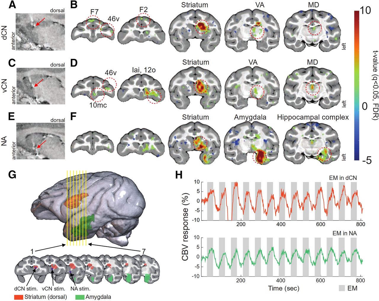
- Figure 8.
Activation maps and temporal patterns of CBV during EM. A, Location of the first stimulation site (dCN, red arrow) on a sagittal view. B, Activation maps during dCN EM overlaid on the D99 atlas with ROIs outlined and labeled (red circles). C, Location of the second stimulation site (vCN, red arrow) on a sagittal view. D, Activation maps during vCN EM overlaid on the D99 atlas with ROIs outlined and labeled (red circles). E, Location of the third stimulation site (NA, red arrow) on a sagittal view. F, Activation maps during NA EM overlaid on the D99 atlas with ROIs outlined and labeled (red circles). G, 3D rendering of the D99 atlas (top) with two ROIs colored (orange, dorsal striatum; green, amygdala). Seven coronal sections are also shown (bottom; yellow lines from top). On sections 1, 2, and 3, purple dots and black arrows mark the dCN, vCN, and NA stimulation sites, respectively. H, Time course of percent signal change (colored lines) measured in the dorsal striatum during EM in the dCN (top) and amygdala during EM in the NA (bottom). Gray bars indicate 30-s stimulation periods and white bars indicate 30 s no stimulation periods (all 13 blocks are shown). To facilitate comparisons, the time courses are plotted with the same ordinate range. This results in some clipping in the top trace. dCN, dorsal caudate nucleus; vCN, ventral caudate nucleus; NA, nucleus accumbens; F2, agranular frontal area F2; F7, agranular frontal area F7; 12o, orbital prefrontal area; 46v, ventro-lateral prefrontal area; 10mc, medial prefrontal area; Iai, intermediate agranular insula area; MD, mediodorsal thalamus; VA, ventral anterior thalamus.


Tables
Availability Manufacturer/source Construction style Actuating mechanism Electrode travel distance Craniotomy required Commercial NeuroNexus, Inc. (MRI-compatible matrix array) Stand-alone N/A Fixed length
(max 15 mm)Yes FHC, Inc. (NeuroPace) Stand-alone N/A Fixed length
based on electrodeNo NaN Instruments, Inc. (NAN MRI drive) Tower style Motorized screw type Max: 120 mm Yes Academic Kern et al. (2008) Stand-alone Ultrasonic actuator Max: 50 mm Yes Grahn et al. (2016) Frame-based stereotactic system Manual screw type Max: 12 mm Yes Dotson et al. (2017) Stand-alone Manual screw type Max: 20 mm Yes Sudhakar et al. (2019) Stand-alone N/A Fixed length
based on electrodeYes
In this issue


